Statechart-Based System Design
Shorter development cycles and the growing complexity of reactive systems as well as their application in safe-critical areas such as flight controllers demand the employment of formal and abstract modeling languages like statecharts in hardware software codesign. Statecharts are based on finite state machines, augmented by the concepts of hierarchy, parallelism, and broadcasting.
Statecharts
and their Execution Times
(Claude Ackad)
STATEMATE is a commercial CAD tool for the specification of reactive systems with statecharts. Such models can be analyzed, animated, and transformed into hardware, software, or both.
Code generators quickly and automatically produce software implementations; the resulting C code mainly consists of if-then-else and switch statements as well as assignments.
For real-time applications, their implementation must satisfy a fixed worst-case execution time (WCET). This WCET depends on the statechart model and the code generator. The WCET is the longest time for a statechart step and corresponds to a guaranteed minimum performance. Model parts with insufficient performance may be replaced by hardware components.
The project SCOT (Statechart Compilation for Optimized reaction Time) aims at the compilation of statecharts into software implementations (machine programs) with an optimized WCET (Fig. 1). Among others, a code generator for statechart models is developed. During code generation, the statechart model is first transformed into an intermediate format (parallel execution graph). By an estimation of the execution times of the nodes and resulting optimizations, the WCET is improved. Using this code generator, the WCET of sample statechart models was reduced by 30-70%, and the minimum performance was equally improved.
Figure 1: From statechart models to optimized machine programs using SCOT
Statecharts
in High-Speed Communication
(Claude Ackad)
New applications such as multimedia or teleconferencing require high transmission power of both, networks as well as terminal devices. Parallel transmission systems offer significantly higher transmissions rates as compared to TCP/IP. Due to parallel transmission functions, statecharts are predestinated for their specification, from which a hardware-software implementation is deduced semi-automatically.
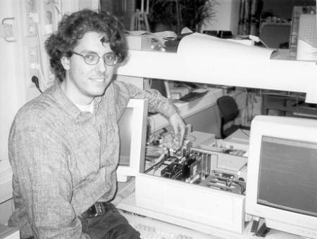
Figure 2: Claude Ackad and a prototype with an FPGA board
The parallel transmission system Patroclos was modeled using statecharts. The mode of operation of Patroclos, e.g. the connection establishment, can be visualized using interactive simulations. The statechart model was divided into a hardware partition for the time-critical parts and a software partition for the uncritical parts. The latter ones were transformed into a machine program. The hardware partition was transformed into a hardware description language (HDL), which was further compiled with the Design Compiler of SYNOPSYS and XACT of XILINX into a configuration of suitable field-programable gate-arrays (FPGAs).
At the beginning, the transmission functions were far too complex for the FPGAs employed. The challenge was the appropriate modification of the statechart model for the hardware partition to enable the generation of a configuration of the XC4020 FPGAs using the tool chain STATEMATE-SYNOPSYS-XACT. Some of the transmission functions required up to 100 attempts. Some resource demanding statechart constructs were identified, which should be avoided. These results have impact on future applications.
Ideas in high-speed communication have to be tested practically. Therefore, a hardware-software platform for Patroclos (Fig. 2) was developed in cooperation with the research group High-Speed Communication and Multimedia Systems (Prof. Zitterbart). It contains FPGAs, an i960 microprocessor for the machine program of the software partition, and an ATM card.
The implementation was successfully put into operation. Two hosts, each carrying one network card, exchanged data. The interaction between i960 and FPGAs was logged with a logic analyzer and special debug interfaces.
Complex
Aircraft Control Systems with Statecharts
(Claude Ackad)
Figure 3: Airbus
In a cooperation with the aircraft producer DaimlerChrysler Aerospace Airbus GmbH, the benefit of statecharts in the development of complex aircraft systems is evaluated. Therefore, the distinct modeling of flight control systems with statecharts, their simulation and coupling with third-party tools like MatrixX is conducted.
Statechart models for core components of the redundancy management and the elevation control for the experimental aircraft VFW 614 as well as the flap control for the Airbus have been developed and simulated. The additional use of STATEMATE description methods such as state transition tables was crucial for model clarity.
Statechart models are often used by persons unexperienced in statecharts. Graphical user interfaces (panels) enable the comfortable evaluation of behavior. They are models of the controlled systems and support the display and modification of important statechart variables through regulators, buttons, and displays. For example, the user is able to generate hydraulic pump failures, on which the statechart model must react appropriately. Fig. 4 contains in the upper part the elevators with two hydraulic pumps each and in the lower part the state of both primary flight control units (PFCUs). The left IOM module has failed and the right IOM has taken control by changing to ACTIV.
Figure 4: Elevation control panel: failure of an IOM module